
Commissioning sequence
-
Isolate the supply. Match connectors and markings to the actual device.
-
Connect the planned BUS channels, LAN, inputs and outputs according to the version-specific wiring diagram.
-
Check connections, circuit separation and required protection. Restore power only after inspection.
-
Configure network and clock. Select the correct channels, register luminaires and configure input/output actions.
-
Verify communication and actual signal responses. Run a test, review its report and create a backup.
Choose a connector
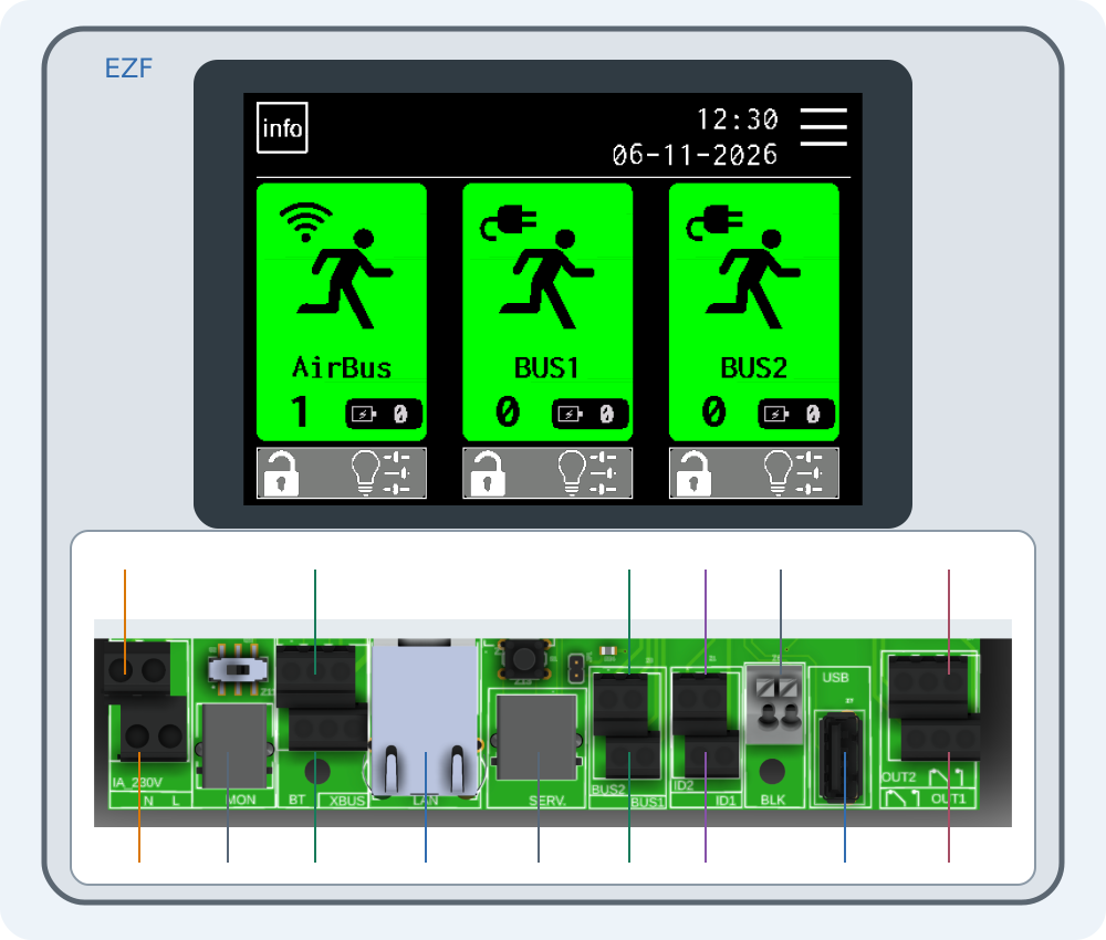
IA 230V — 230 V control input
IA 230V receives a mains-voltage control signal. It is separate from the N/L supply terminals. In AC input settings, select target channels, condition and action, save and verify the response to the actual signal.
N / L — Controller power supply
N and L supply the controller with 230 V AC, 50 Hz as specified for the device version. Qualified personnel must work with the supply isolated and verified. Graphic colors do not define terminal order.
MON — External diagnostic module
The manual assigns MON to an external diagnostic module. Use the specified module and cable. A similar socket shape does not imply Ethernet compatibility.
LAN — Wired LAN
LAN connects the controller to the local network. After connecting the cable, select LAN in network settings and configure DHCP or an appropriate static IP address. Connecting a cable alone does not switch the interface from Wi-Fi.
SERWIS — Service connector
The connector marked SERWIS is for the specified service functions. Use the appropriate equipment and procedure for the device version. It does not replace the LAN port.
BUS2 — BUS2 — wired luminaires
A separate channel for wired luminaires. The manual diagram specifies J-Y-(ST)-Y 2 × 2 × 0.8 mm cable. Follow the markings and polarity of the actual device; do not connect BUS1 to BUS2 or to mains voltage. After commissioning, select the correct channel and check the luminaire list.
BUS1 — BUS1 — wired luminaires
A separate channel for wired luminaires. The manual diagram specifies J-Y-(ST)-Y 2 × 2 × 0.8 mm cable. Follow the markings and polarity of the actual device; do not connect BUS1 to BUS2 or to mains voltage. After commissioning, select the correct channel and check the luminaire list.
ID2 — ID2 — volt-free input
Input for an external contact, such as a pushbutton or relay. Do not apply mains voltage. In PFE settings, choose input 1 or 2, set NO/NC, target channels and action, save and verify the response to contact changes.
ID1 — ID1 — volt-free input
Input for an external contact, such as a pushbutton or relay. Do not apply mains voltage. In PFE settings, choose input 1 or 2, set NO/NC, target channels and action, save and verify the response to contact changes.
BLK — Connector marked BLK
The drawing shows BLK, but does not specify its pinout or electrical ratings. Check the wiring documentation for the actual device version before use. Do not treat it as a 230 V input.
USB — USB storage
The USB storage port supports data import, export and full backups. Use compatible FAT32/exFAT storage with MBR. Do not remove it during writes. A full USB backup also requires a working SD card.
OUT2 — OUT2 — relay output
A volt-free contact for signaling a selected controller state to an external system. Choose the relay and condition, such as fault, test or OK, in output settings. It does not supply its own voltage. Check COM/NO/NC and permissible load on the device and in its documentation.
OUT1 — OUT1 — relay output
A volt-free contact for signaling a selected controller state to an external system. Choose the relay and condition, such as fault, test or OK, in output settings. It does not supply its own voltage. Check COM/NO/NC and permissible load on the device and in its documentation.
BT — Remote signaling panel
BT connects the remote signaling panel. Connection details and parameters will be covered in a separate instruction.
XBUS — GEMINI supervision bus
XBUS is the supervision bus for integration with GEMINI series devices. Integration has its own forthcoming instruction; socket shape alone does not define pinout or electrical parameters.